
100G QSFP28 Multimode LC Duplex CWDM4
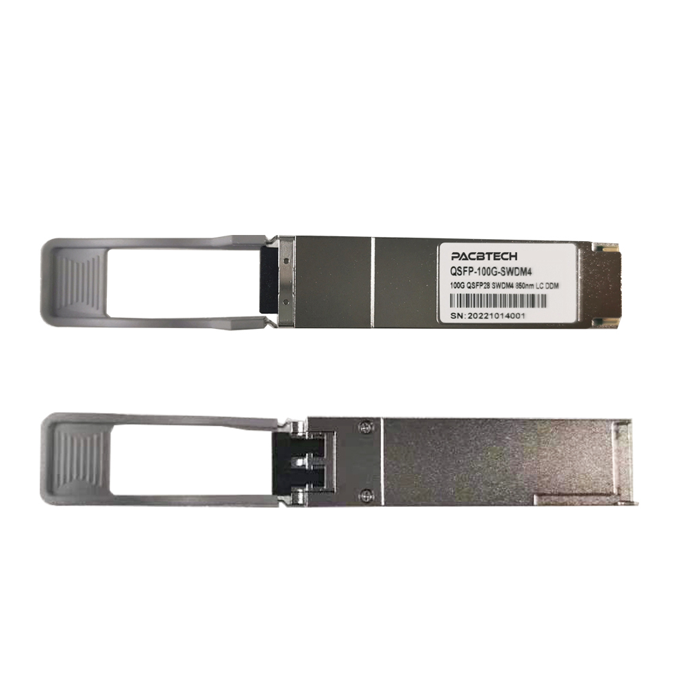


100G QSFP28 SWDM4 Optical Tranceiver Multimode Duplex LC
Distance:
OM3-75Meters
OM4-100Meters
OM5-150Meters
The 100G QSFP28 SWDM4 transceiver modules are designed for use in 100G Ethernet links over duplex multimode fiber. Four channels/lanes in the 850-940nm region @ 25.78Gbps to transport the Ethernet signal. Digital diagnostics functions are available via an I2C interface, as specified by the QSFP28 MSA.
Applications
100G Ethernet over Duplex MM
Feature
Compliant with QSFP28 MSA
Compliant with SWDM MSA
Compliant with IEEE802.3bm CAUI-4
Hot-pluggable QSFP28 form factor
4x25Gb/s 850mm VCSEL-based transmitter
Supports 103.1Gbps aggregate bit rate
Power dissipation<3.5W
Maximum link length of 150m on OM5 multimode Fiber
Case temperature range of 0°C to 70°C
Duplex LC receptacles
CAUI-4 electrical interface
RoHS compliant
1. Absolute Maximum Ratings
Parameter | Symbol | Min | Max | Units |
Storage Temp Range | Ts | -40 | +85 | ℃ |
Supply Voltage | Vcc | -0.5 | 3.6 | V |
Relative Humidity | RH | 15% | 85% |
2. Operating Conditions
Parameter | Symbol | Min | Max | Units |
Case Temp-Operating | Tcase | 0 | 70 | ℃ |
Supply Voltage | Vcc | 3.14 | 3.46 | V |
Power Consumption | P | 3.5 | W | |
Link Distance on OM3 Fiber | 75 | M | ||
Link Distance on OM4 Fiber | 100 | M | ||
Link Distance on OM5 Fiber | 150 | M |
3. Optical Characteristics
Transmitter Parameter | Lane | Min | Typical | Max | Unit | Note |
Signaling rate, each lane | 25.78125±100ppm | Gb/s | ||||
Lane Wavelength Range | Lane0 | 844 | 858 | nm | ||
Modulation Format | NRZ | |||||
Difference in launch power between any two lanes | 4.5 | dBm | ||||
RMS Spectral width | 0.59 | nm | 1 | |||
Optical Modulation Amplitude (OMA), each lane | -5.5 | 3 | dBm | 2 | ||
Average Launch Power per Lane @ TX Off State | -30 | dBm | ||||
Launch Power in OMA minus TDEC | Lane0 | -7 | dBm | |||
Transmitter and Dispersion Eye Closure | Lane0 | 4 | dB | 3 | ||
Extinction Ratio | 2 | dB | ||||
Optical Return Loss Tolerance | 12 | dB | ||||
Encircled Flux | ≥86% at 19 um ≤30% at 4.5 um | 4 | ||||
Transmitter eye mask definition {X1, X2, X3, Y1, Y2, Y3} | {0.3,0.38,0.45,0.35,0.41,0.5} | |||||
Notes: | ||||||
Receiver Parameter | Lane | Min | Typical | Max | Unit | Note |
Signaling rate, each lane | 25.78125±100ppm | Gb/s | ||||
Lane Wavelength Range | Lane0 | 844 | 858 | nm | ||
Lane1 | 874 | 888 | ||||
Lane2 | 904 | 918 | ||||
Lane3 | 934 | 948 | ||||
Modulation Format | NRZ | |||||
Damage Threshold | 4.4 | dBm | ||||
Average Receive Power, each lane | Lane0 | -9.5 | 3.4 | dBm | ||
Lane1 | -9.4 | |||||
Lane2 | -9.4 | |||||
Lane3 | -9.4 | |||||
Receiver Power, each lane (OMA) | 3 | dBm | ||||
Receiver Reflectance | -12 | dB | ||||
unStressed Receiver Sensitivity(OMA) | Lane0 | -8.2 | dBm | 1 | ||
RX_Los_Assert | -30 | dBm | ||||
RX_Los_De-ASSERT | -12 | dBm | ||||
RX_Los_Hysteresis | 0.5 | dBm | ||||
1.unstressed sensitivity at BER of 5E-5(pre FEC) | ||||||

Copyright © 2025 . Pacific Brands Technology Limited All rights reserved.